Alternate battery charger-regulator circuits, presented for information only.
I didn't build these because I had the gel battery, and the circuits of Figs 2 and 3 proved to be perfectly adequate.
See: Long-Range Wireless Gate Annunciator
Rainy Day Version
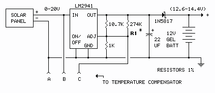
Had the charging panel been unable to maintain the battery adequately, a low dropout charging regulator could have been used to reduce the headroom requirement from about 2.35 volts to around 0.85 volts. This would allow the battery to be charged (some) under most overcast situations. A circuit is shown below.
Low-Dropout Charger-Regulator Circuit
Figure 4

| *R1 is selected for 14.06V, measured at the battery terminals, with jumper J1 (Figure 3) removed. J1 jumper removal simulates 0°F (installed for normal operation). Had the temperature compensator circuit not been used (nothing connected to A, B or C), R1 would be selected for 13.6V. |
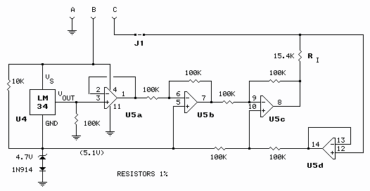
Temperature Compensator for Figure 4
Figure 5

U4 = LM34 Fahrenheit Temperature Sensor U5 = LM324 Quad Low-power Op-amp
Note: This temperature compensator circuit is not compatible with the Figure 2 regulator circuit.
No-Regulator Option
Another option would be to eliminate the charging regulator entirely, reducing the dropout to about 0.35 volts, but, unless the solar panel is very small and the battery very large, it would not be a good idea. A "12-volt" solar panel can easily put out over 20 volts on a bright sunny day, risking battery overcharge.
NiMH/NiCd Version
(This might have been a good choice had I not had the gel battery.)
If NiMH or NiCd batteries were being used, a constant-current (CC) charging circuit would be the correct choice. The charge rate would usually be set at 0.1C, that is, one tenth battery capacity. Load current would normally also have to be included, but in this case, load current is small and intermittent enough to be ignored. The circuit would look something like this:
Constant-Current Charger
Figure 6

The charging regulator is not needed if the short-circuit current rating of the solar panel does not exceed 0.1C, one tenth battery capacity.