Photos
200-Watt Class-E AM Transmitter
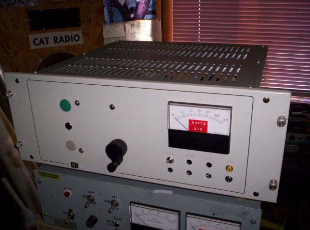
The 200-Watt Transmitter as Built
(1710 kHz version)
The meter is a directional wattmeter.
A multimeter can be connected to the test jacks on the lower right to monitor driver current during tune-up.
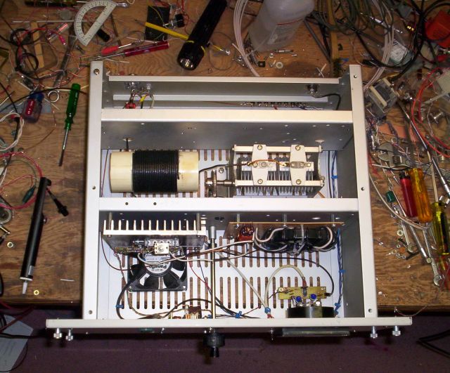
Transmitter Interior
Shows output filter components L1 (left center section) and C2 (right center section).
L1 is wound with 14 AWG Romex on 2" (I.D.) PVC water pipe.
C2 is a 420 pF transmitting-type air variable, adjusted via a shaft to a knob on the front panel.
The output transistors are mounted on the heatsink on the left front divider panel.
The output transformer is on the right front divider panel.
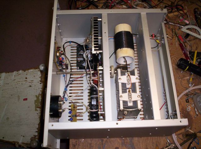
Another View of the Transmitter Interior
The exciter board is mounted on the front panel on the left.
The current sensing transformer for the directional wattmeter can be seen at the upper right.
The wattmeter driver (AD835) is at the lower left.
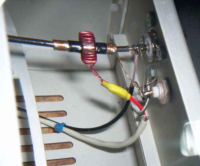
Close-up of the Current Sensing Transformer
The upper connector is the transmitter output, the lower connector is for connecting a monitor scope (Test Point 1).
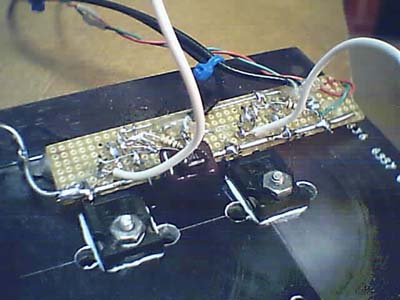
Output MOSFETs
The output transistors are shown mounted on the heatsink.
The driver circuitry is mounted on the small board.
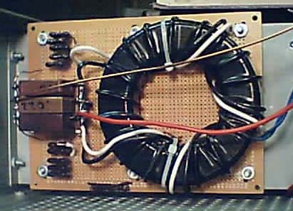
Output Transformer
With resonating and bypass capacitors.
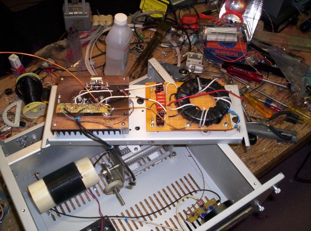
Output Transistors/Transformer
Mounted on front divider panel before installation.
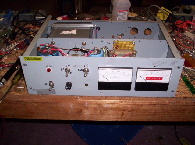
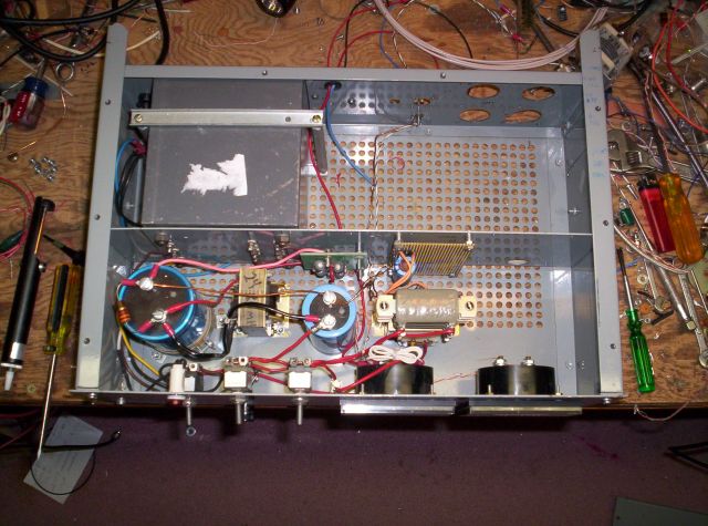
Power Supply
Control switches, ammeter and voltmeter.
Power Supply Interior
The gray thing at the left rear is the power transformer.
The filter components are in the front section.
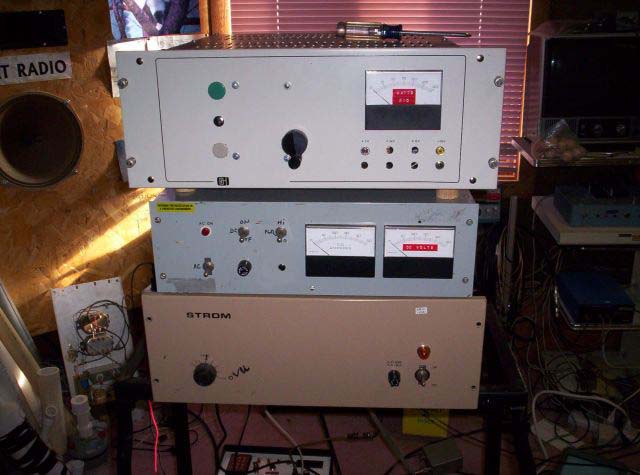
The Class-e Transmitter with its Power Supply and Modulator
The modulator is the brown thing under the gray power supply.
The modulator was a public address amplifier in a previous life.
Rear View
Cats
Related Links
