Find on this page | Range Calculator/Estimator
|
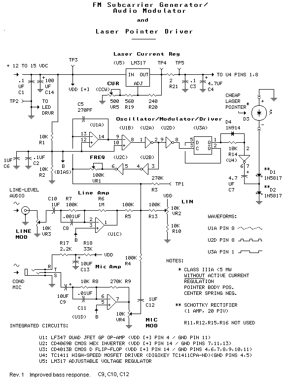
If you'd like to experiment with point-to-point (free-space, without a glass fiber) light-beam voice or other audio communications, or with music transmission (say, to a remote clandestine radio transmitter), these circuits might be of interest to you. The high-fidelity circuits employ a cheap laser pointer as the light source and a readily available photodiode as the detector. The system has been successfully demonstrated to a distance of 6.5 miles (10.5km). Lasers are inherently non-linear devices; laser diodes happily operate only in a narrow range of drive currents. Too little current and the diode refuses to "lase". Too much and the diode self-destructs. Thus, efforts to directly modulate a laser with an analog signal are usually unsatisfactory. The vast majority of laser modulators are of digital design; the modulator switches the laser between two discreet current levels, conveying information in the data encoded in the drive signal. In this case, the 'data' is an FM subcarrier operating at around 75 kHz, and the laser current levels are 0 and 30 mA (adjustable). Likewise, photodetectors operating in the real world of ambient light noise sources, without benefit of a glass fiber transmission medium, suffer from non-linearities of their own. The FM subcarrier is for the most part immune to detector non-linearity. The transmitting circuit is shown in Figure 1. |

|
The circuit uses a method of generating FM called slope modulation. Integrator U1a, comparator U1b and limiter U3 form a free-running FM oscillator/modulator operating at twice the operating output frequency. Integrator U1a is the heart of the modulator. The output of U1a is a linear ramping voltage of either positive or negative slope. The slope is determined by 1) the value of the integrating capacitor connecting pins 13 and 14 of U1a and 2) the sum of currents from U1c, U1d and FREQ ADJ and LINEARITY ADJ potentiometers at the summing point (pin 13) of the integrator. Negative feedback current from U2, through the FREQ adjust potentiometer, causes the circuit to oscillate at a frequency determined by the combined positive and negative slopes of the U1a output signal. The output signal (U1a pin 14) is a non-symmetrical (scalene) triangle wave. The degree of asymmetry determines the period and thus the frequency of the output signal; the greater the asymmetry, the lower the frequency. By controling the integrators's output slope, the combined input currents (from the above-mentioned sources) determine the instantaneous oscillator frequency. The output signal from U1a is presented to comparator U1b. The output of U1b will either be 'high', near the power rail voltage, or 'low', near ground, depending on whether the pin 9 voltage is above or below the reference voltage on pin 10. Limiter U2 shortens the rise and fall times of the U1b output signal. U2 provides the negative feedback signal to the integrator, as explained above, and also clocks output divider U3a. U3a divides the signal frequency by 2 and restores symmetry. U4 is the laser driver. When the output of the D flip-flop (U3a) is low, the driver connects the laser current supply to the 4.7 uF coupling capacitor. This causes the lower Schottky diode to conduct, charging the capacitor. When the D flip-flop is high the driver connects the capacitor to the ground rail. This discharges the capacitor and causes the upper diode to conduct. The discharge current is delivered to the laser pointer. The driver's internal resistance and the forward voltage drop of the diodes work in conjunction with the pointer's internal resistor to limit current flow through the circuit. Laser current can be monitored with a multimeter connected to TP4 and TP5. Current flow from the current regulator is actually one-half the instantaneous current flow through the laser diode, since laser current flows for exactly one-half of the time. The 2-ohm scaling resistor establishes a nominal one-to-one voltage drop to instantaneous laser current relationship. Current through the laser diode causes it to produce coherent light of a wavelength and dispersion typical of a laser diode. The output of the laser diode is a series of light pulses in step with the output of the FM subcarrier generator. The laser is simply a cheap key-chain laser pointer. In order to work with the pulse modulator, the laser must be of the type not equipped with active current regulation. In other words CHEAP. (Given a choice of laser pointers, would-be builders of this circuit should select the CHEAPEST one available - buy several.) Cheap pointers are equipped only with an internal fixed-value current-limiting resistor (value around 50 ohms). At the time of this writing, such a pointer was available here, also here. You might also find one at your local 'dollar' store. Line and microphone amplifiers U1c and U1d amplify and isolate their respective input signals and present them, via the 100k resistors, to the slope modulator, as explained above. The amplifier circuits also each introduce a 6 dB per octave high-frequency pre-emphasis, starting at around 1600 Hz.
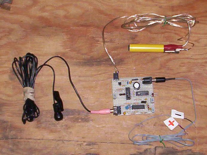
Prototype laser pointer modulator.The black thing on the left is a condenser microphone. The yellow thing at the top is a cheap laser pointer (the pushbutton on the pointer, on the far side of the yellow body in the photo, is taped down for operation). The gray cord at the lower right is for connecting to a 12-15v DC power source. |


|
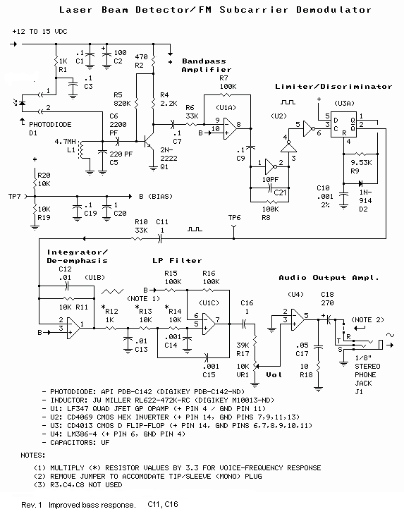
Beam concentration can raise the signal to noise ratio of the detected optical signal, and may be necessary, depending on the transmitter-to-receiver distance and other factors. Here's a Laser Beam Concentrator to mount your photodiode in for increased sensitivity and range. The concentrator was successfully used with the prototype modulator/demodulator system to establish an audio link over a distance of 6.5 miles. Photos of System DX Tests
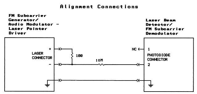
System AlignmentThe laser pointer audio modulator requires alignment. The alignment procedure uses the discriminator in the demodulator as a 'frequency meter'. The procedure is not difficult but should be followed carefully for best results. Figure 3 shows the modulator/demodulator interconnection used for alignment. |

|
Basic alignment:
Fine Tuning:The above procedure should produce acceptable fidelity for most applications. Further improvement might be acheived with a tone generator and oscilloscope and/or distortion analyzer as follows:
Setting laser current:
Setting modulation levels:
|
Schematics produced with DCCAD.